

Semi-Metallic / Spiral Wound
Spiral Wound Gaskets
Metal winding. Soft filler. A resilient seal for industrial flanged joints, selected around your flange geometry and service conditions.
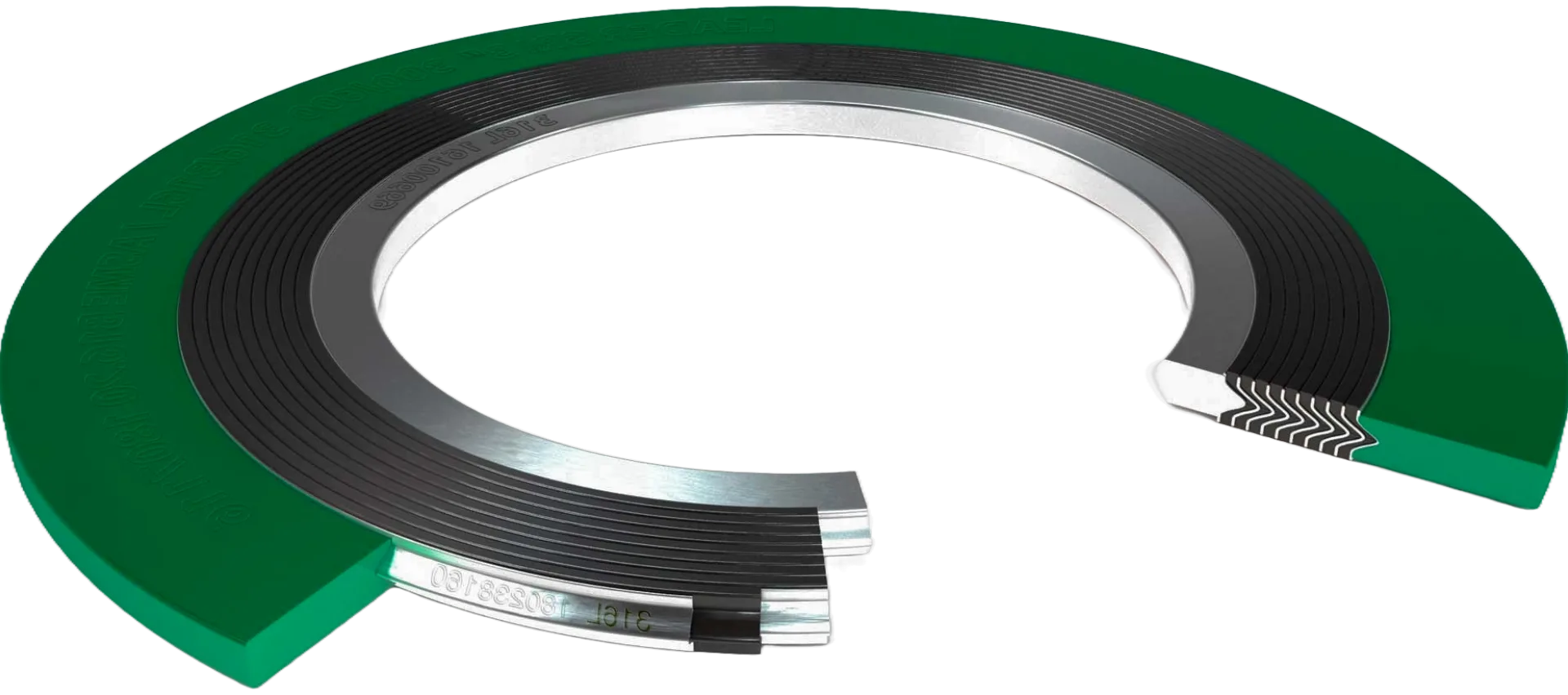
THE CONSTRUCTION
Metal strength.
Soft-material sealing.
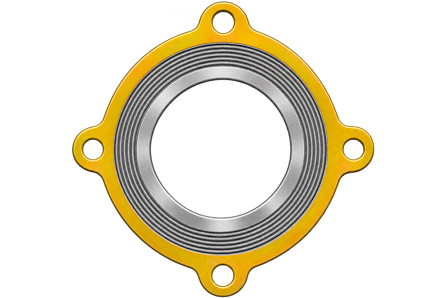
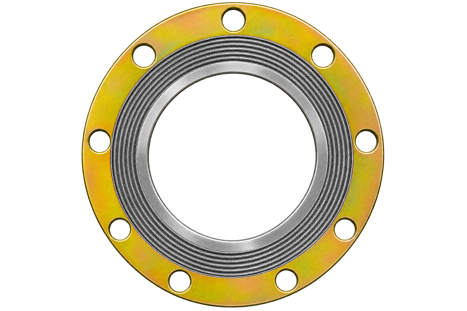
Profiled metal strip and soft filler are wound together. The metal provides resilience; the filler conforms to the flange faces under assembly load.
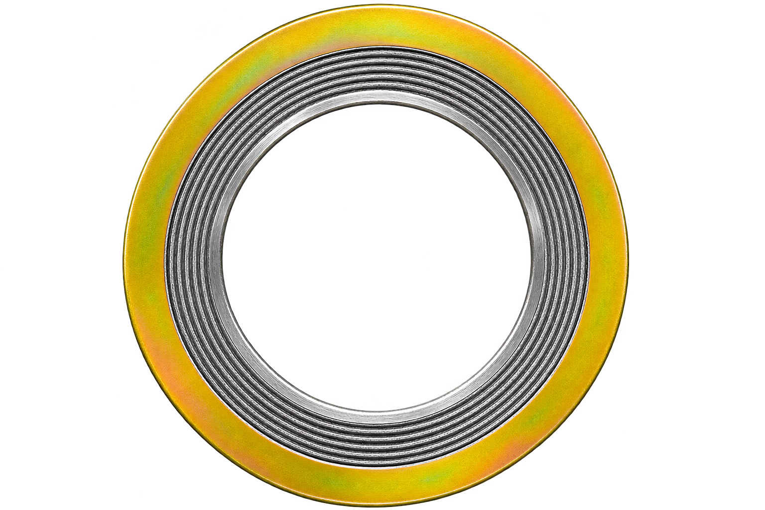
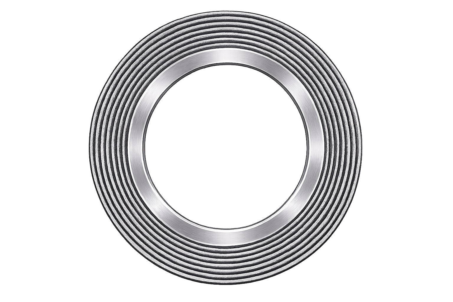
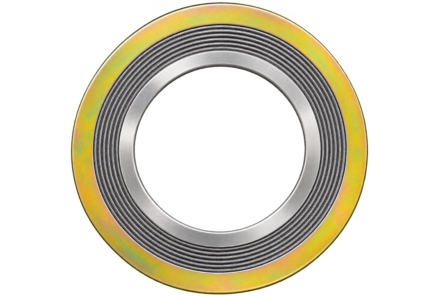
The winding forms the seal. Inner and outer rings support or locate it, according to the flange and specification.
FamilySemi-metallic
Sealing elementMetal + soft filler
Configurations shownSix arrangements
Oil & petrochemical
Flanged joints in hydrocarbon processing and associated plant piping.
Chemical processing
Process connections with winding and filler selected for chemical compatibility.
Steam & power
Steam and thermal-service joints with materials matched to the complete operating duty.
Heat exchangers & valves
Equipment joints designed to accommodate a spiral wound sealing element.
SPECIFY WITH CONFIDENCE
Three checks before you specify.
Pressure and temperature limits depend on the complete joint and material combination.
01 / Materials & service
Stainless-steel winding with graphite or PTFE filler is common. Check fluid and temperature compatibility; filler capability alone does not define the assembly rating.
02 / Dimensions & standards
Confirm flange standard, size, class, facing and bore. ASME B16.20 covers specified gasket requirements; special locating designs need an approved drawing.
03 / Rings & installation
Check inner-ring requirements, especially with PTFE filler. Use sound, clean faces and the specified bolt load. Do not reuse compressed gaskets.
Technical reference: ASME B16.20 scope. Images illustrate configurations; dimensions and material specifications must be confirmed for the enquiry.
LET’S DEFINE YOUR REQUIREMENT
The right configuration starts with the right details.
Share the flange size and standard, pressure class, ring arrangement, winding and filler materials, service conditions and quantity. Include a drawing for a special design.